
Shopping Cart
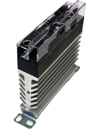
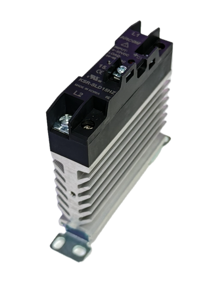
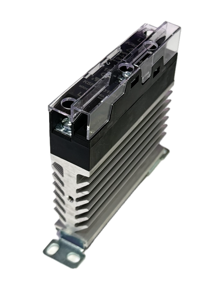


Last items in stock
Slim-Type SSR — Slimmer Choice, Widened Space, Lower Costs
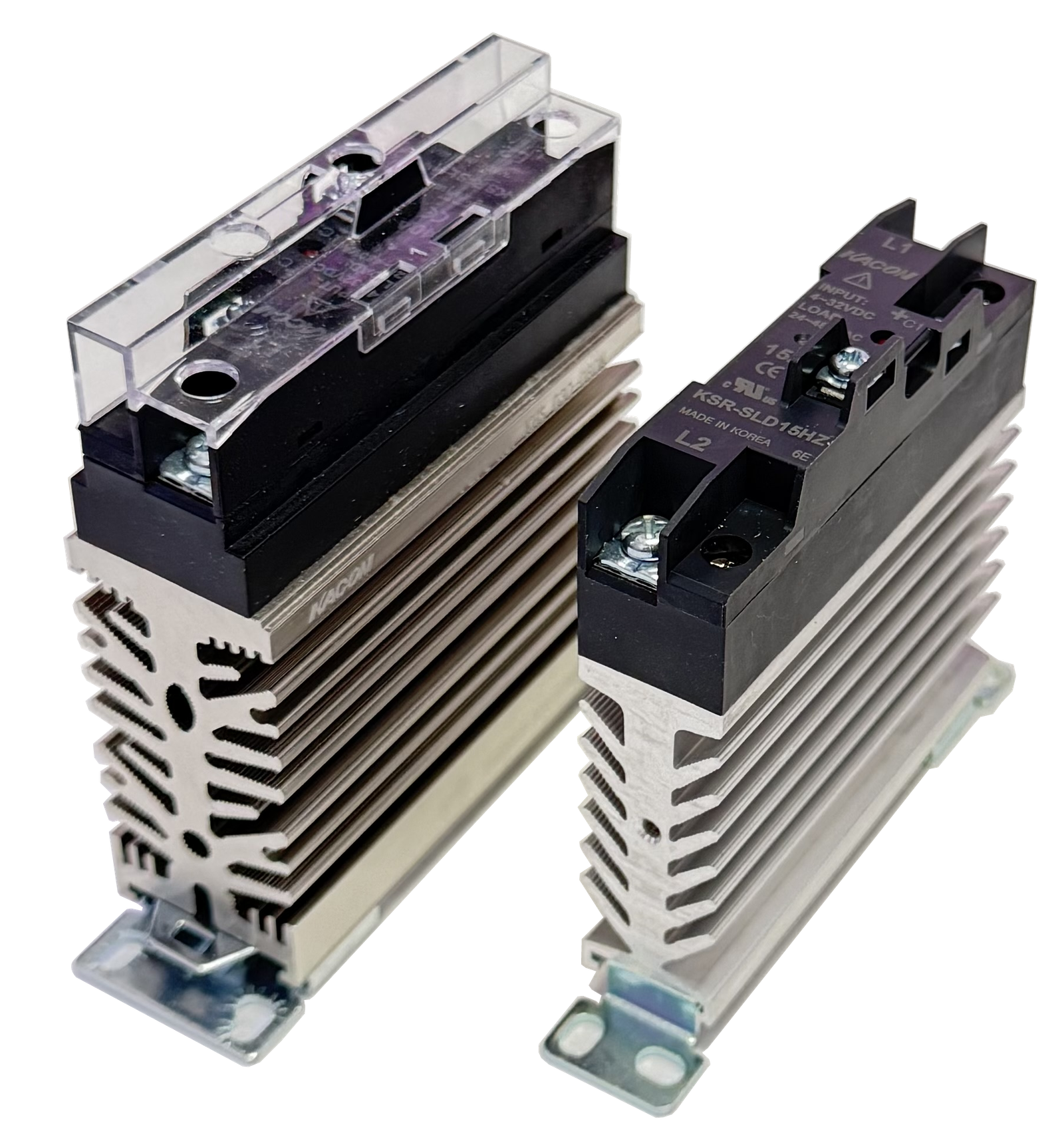
Panel space is expensive. The KSR-SL Series trims relay width down to 20.0mm (15A/25A) and 30.0mm (40A) — noticeably narrower than typical competitor units — so a bank of 10 relays takes up meaningfully less DIN rail length without sacrificing heat dissipation or lifespan.
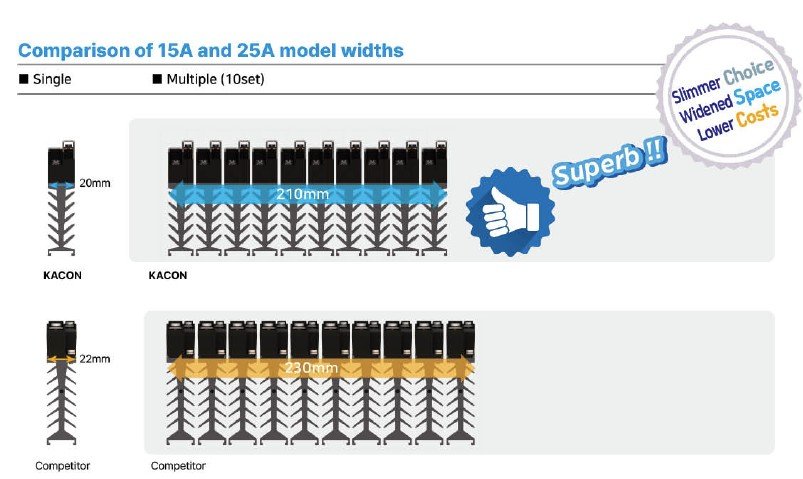
10-unit bank comparison, 15A/25A models: KACON KSR-SL – 210mm total vs. a comparable competitor unit – 230mm total. The 40A model shows the same advantage (310mm vs. 460mm for 10 units).
CE, UL Standard Product
| Model Name | Code | Detail | |||
|---|---|---|---|---|---|
| KSR-SL | □ | □ | □ | □ | Slim-type SSR |
| Control input voltage | D | 4~32 VDC | |||
| Rated load current | 15 | 15A | |||
| 25 | 25A | ||||
| 40 | 40A | ||||
| Operating load voltage | L | 24 ~ 240 VAC (for low voltage) | |||
| H | 24 ~ 480 VAC (for high voltage) | ||||
| Operation Method | Z | Zero-Cross Switching (Standard Product) | |||
| R | Random Switching (Custom-Made) | ||||
* For inquiries about the bimetal temperature switch (60°C, 80°C) options, please contact the head office directly.
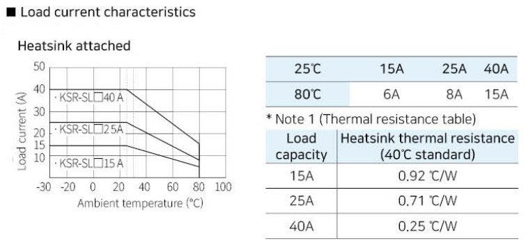
| Load capacity | Heatsink thermal resistance |
|---|---|
| 15A | 0.92 °C/W |
| 25A | 0.71 °C/W |
| 40A | 0.25 °C/W |
| Parameter | 15A | 25A | 40A |
|---|---|---|---|
| Model (Low voltage, Zero-cross) | KSR-SLD15LZ | KSR-SLD25LZ | KSR-SLD40LZ |
| Model (High voltage, Zero-cross) | KSR-SLD15HZ | KSR-SLD25HZ | KSR-SLD40HZ |
| Model (Random switching) | KSR-SLD15LR / HR | KSR-SLD25LR / HR | KSR-SLD40LR / HR |
| Operating load voltage | 24 ~ 240 VAC (low) / 24 ~ 480 VAC (high), 50/60 Hz | ||
| Peak voltage (non-repetitive) | 1,600V | ||
| Rated load current | 15A | 25A | 40A |
| Input current, 60Hz (8.3ms non-rep.) — low/high V | 170A / 170A | 260A / 250A | 420A / 370A |
| Input current, 50Hz (10ms non-rep.) — low/high V | 160A / 170A | 250A / 230A | 400A / 350A |
| Leakage current | 20 mA max. | ||
| Output ON voltage drop | 1.6V (R.M.S) max. | ||
| Rated (input) voltage | 5 ~ 24 VDC | ||
| Operating voltage range (ON) | 4 ~ 32 VDC | ||
| Recovery voltage (OFF) | 3V max. | ||
| Input impedance | 4 kΩ max. | ||
| Current consumption | Constant current method: 14 mA max. | ||
| Response speed | 1/2 cycle + 1ms max. ("R" type: 1ms max.) | ||
| Insulation resistance | 500VDC, 100 MΩ (between input, output, and case) | ||
| Withstand voltage | 2,500VAC (1 minute at 60Hz) | ||
| Rated impulse withstand voltage (Uimp) | 2,500V | ||
| Vibration resistance | 10~55Hz, double amplitude 1.5mm, 2 hrs per axis (X,Y,Z) | ||
| Shock resistance | 1,000 m/s², 3 times per axis direction | ||
| Storage temperature | -30 ~ 90°C | ||
| Ambient operating temperature | -30 ~ 80°C (no condensation) | ||
| Ambient operating humidity | 45 ~ 85% RH | ||
| Pollution grade | Grade 2 | ||
| Bolt tightening torque | Input terminal: 0.05 Nm / Output terminal: 0.25 Nm | ||
| Usage | Resistive load | ||
| Applicable standards | CE (EN 60947-4-3), UL, RoHS2 | ||
| Weight | 190g (15A/25A) | 300g (40A) | |
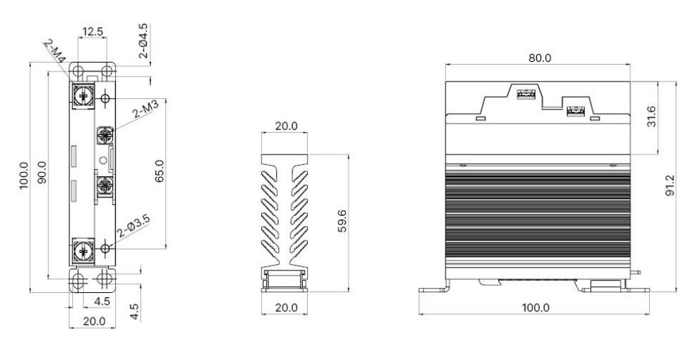
15A / 25A models
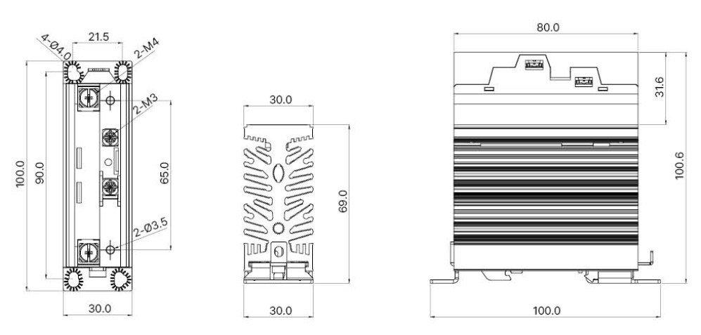
40A model
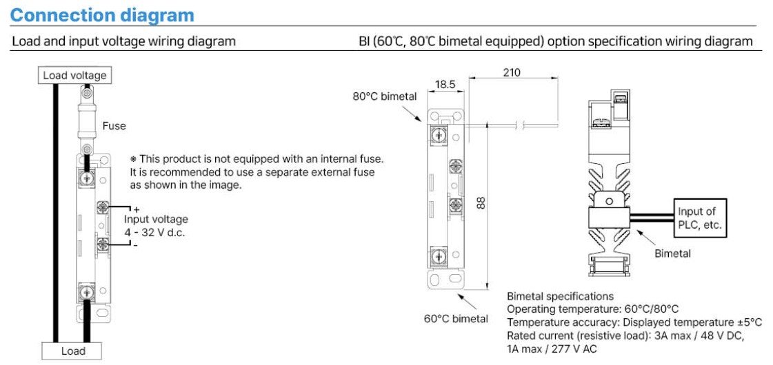
This product is not equipped with an internal fuse — use a separate external fuse as shown. Optional 60°C / 80°C bimetal temperature switch versions are available (rated 3A max / 48VDC, 1A max / 277VAC) — contact the factory for custom-made options.
Load current vs. ambient temperature (heatsink attached)
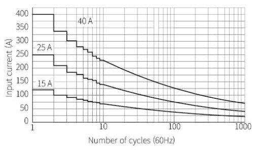
Input (inrush) current vs. number of cycles
| Terminal wiring | Minimum | Maximum |
|---|---|---|
| Input terminal | 1 x 0.5mm² (1 x AWG20) | 1 x 1.5mm² (AWG16) or 2 x 1.5mm² (2 x AWG16) |
| Output terminal | 1 x 1.5mm² (1 x AWG16) | 1 x 16mm² (AWG6) or 2 x 6mm² (2 x AWG10) |
Load-side output terminal width is 9.5mm and input terminal width is 6.8mm — use terminals equal to or smaller than these dimensions and tighten to the rated torque. For actual load currents of 35–40A, keep ambient temperature at 25°C or below. When wiring a 40A load, use 10SQ wiring with a clamping unit or lug.


